Building Avionics for a Rocket Ship Treehouse
Page 3
October 10, 2009 -- v1.1 PCBs arrive!
|
|
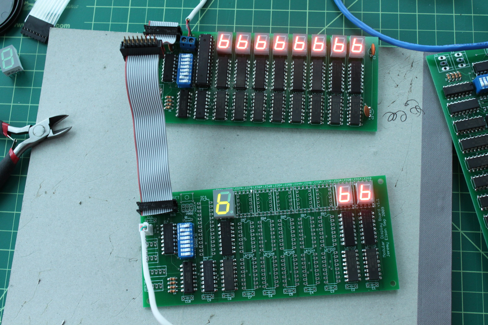
The v1.1 boards were more evolutionary than anything else, as you might know if you've read the rest of the entries in painstaking detail. Perhaps the most visible change is that it now supports larger LEDs (0.56", vs the original that only supported 0.39"). Through some clever routing, a single board can take either size of LED, or a combination. v1.1 also have some convenience features: mounting holes, a reset button, more analog-to-digital converter pins now available, a joystick port (a single header with 2 ADC inputs, plus a GPIO input for the trigger button), and so forth.
To the right is a picture I took of the first v1.1 board with LEDs soldered in, showing that both the larger (green) and smaller (orange) LEDs work together. This v1.1 board doesn't have a processor yet; it's being controlled via the data bus by one of the older v1.0 boards.
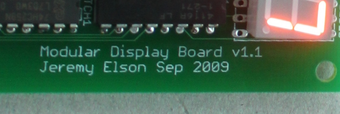
I also have a glamour shot of my "signature" on the new PCBs. By v1.1 I'd figured out how to add custom silkscreening so I put my name on it.
October 19, 2009 -- Building a High Precision Clock
|
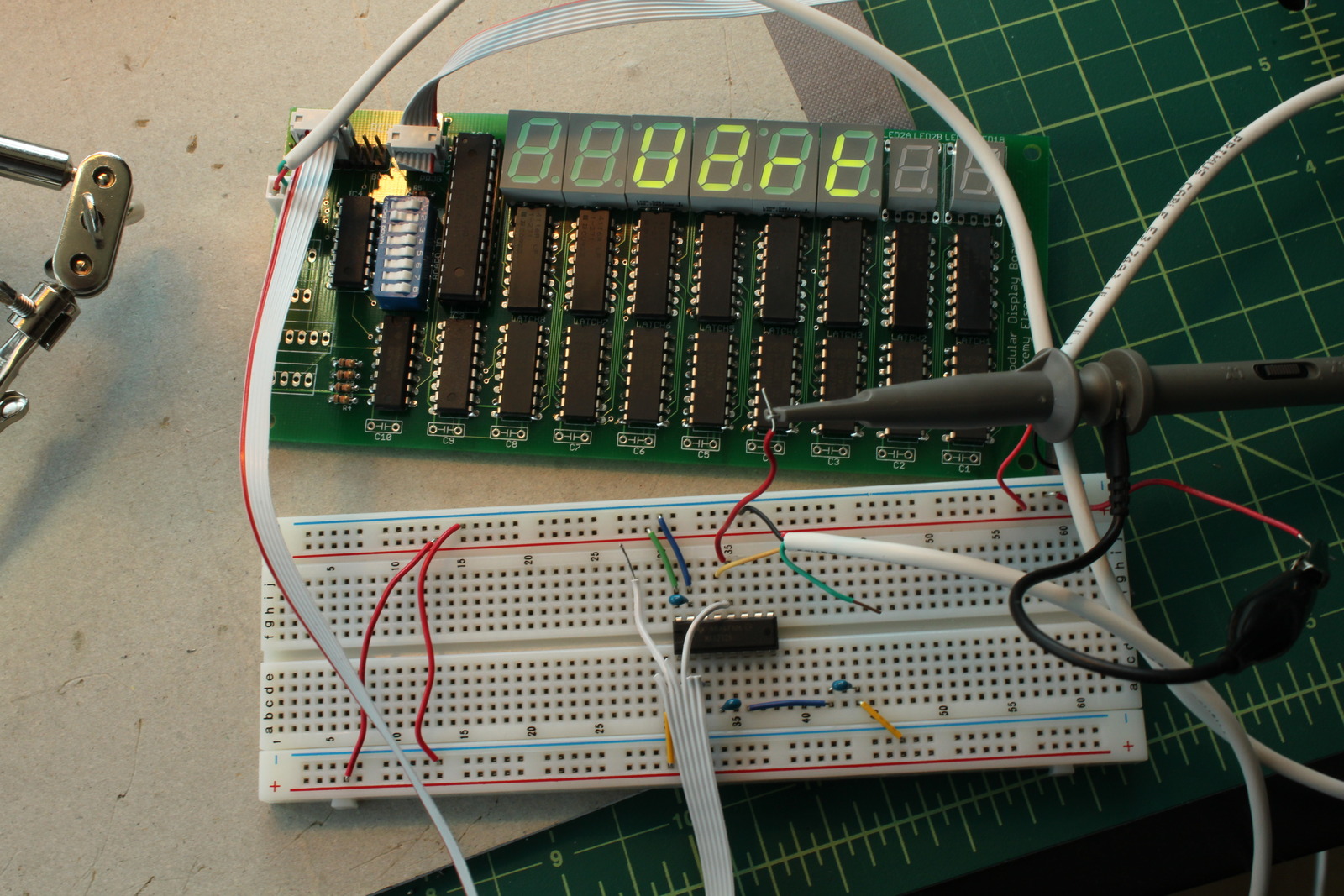
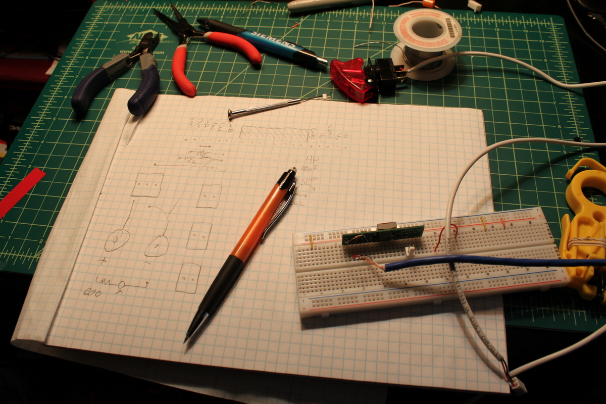
| The original bread-boarded prototype of the UART interface to the PC. The extra chip is a MAX-232 level converter that converts between serial port voltages and microcontroller voltages. Also visible is a probe of my oscilloscope. |
|
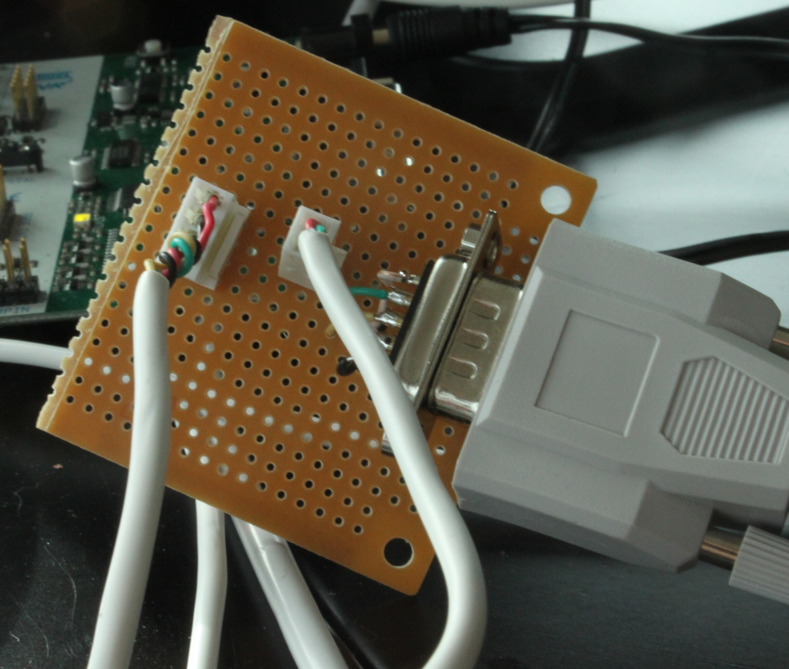
| The final soldered version of the PC side of the clock interface. Serial port data (right) and 5v power (center) are combined into a single 4-conductor cable (left). |
|
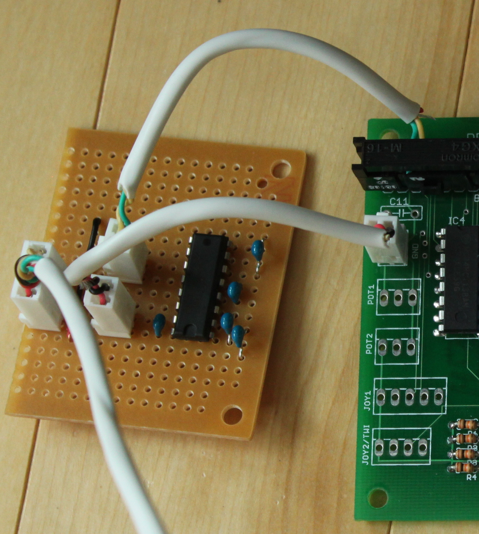
| The clock side of the interface board. The 4-conductor cable is broken back out into serial and power. The MAX-232 converts the serial voltages down to TTL voltages. |
Of course, having written a time-sync dissertation, this clock would need to be accurate. My original plan was to signal the start of each second using a single GPIO line, but Jon convinced me to use a full-fledged serial port to send complete time messages. After some resistance (I was afraid the serial port would be too complex) I agreed.
The first step was to establish a data link between my PC and the board. I bought some MAX-232's, which are chips that convert the voltage used by a PC serial port to the voltage used by typical microcontroller. I prototyped an interface board that would take a PC serial port, short-circuit the flow control lines like a null-modem does, and put the 2 data lines into the MAX-232. I wrote code on the controller to configure the UART, accept serial port interrupts, timestamp them with high precision, and enqueue the characters. As a first test, I wrote a simple program that would just read characters and display them. It was surprisingly cool: I could type on my PC keyboard, and see messages scroll across the 7-segment LEDs!
Next, using my newfound power to get messages from the PC to the board, I set out to get my clock to tick correctly. I wrote a small program that runs on the PC which sends a message to the serial port once every minute, precisely at the beginning of the minute, telling the board what time it is. (The PC's clock is synchronized using NTP, via the Internet.) The clock board lets the clock run free in between the messages; when it gets one, it both sets the time and trains its oscillator so that the length of coming free-running minute will be accurate. It annoys me that most time-sync software doesn't do this; usually, they just jump the clock to the right value every few minutes, giving you a clock with a sawtooth pattern.
Finally, I built a permanent pair of small connector boards so I'd be able to feed both power and serial data into a single 4-conductor cable to run from my office PC to the clock.
If this sounds like a project that consists mostly of a hundred tiny little details, you're right. But the result is awesome, and I'd estimate remains accurate to within 20ms of the PC's clock throughout the entire minute between pulses:
It's now hanging on the wall outside my office. If you're ever at Microsoft, stop by 99/2374 and take a look at it!
October 25, 2009 -- Joysticks controlling thrusters -- it
works!
 Today was a big day: I got a big and complicated part of the system to
work properly. Even if I stop work today and never assemble another
panel, the piece I have working right now would be enough to make the
rocket cool. Specifically, I have the joystick controlling the
rocket's thrusters (i.e., solenoid air valves).
Today was a big day: I got a big and complicated part of the system to
work properly. Even if I stop work today and never assemble another
panel, the piece I have working right now would be enough to make the
rocket cool. Specifically, I have the joystick controlling the
rocket's thrusters (i.e., solenoid air valves).
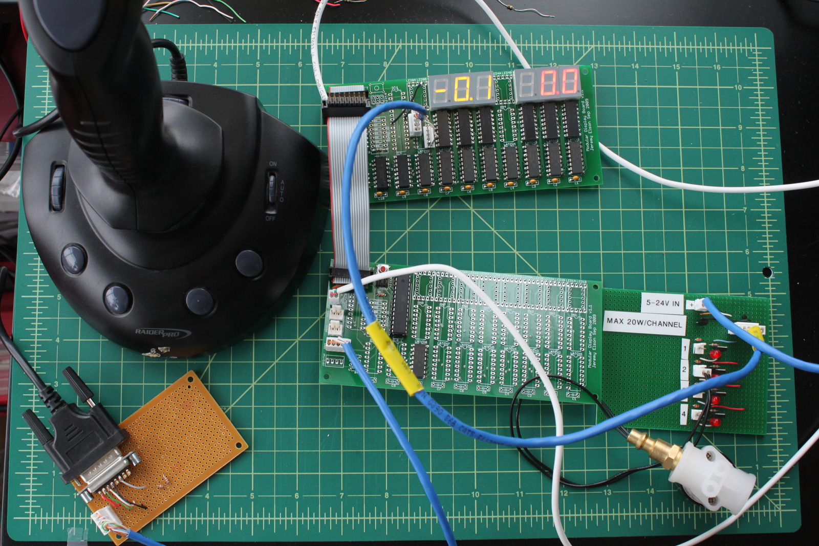
I don't think I really appreciated how complex this project had become until I sat down yesterday to make this all work. I was shocked to discover that there are no less than 6 separate components that must be chained together in a long line:
- The joystick.
- A small joystick interface board with two resistors, forming two voltage dividers that can be read using the processor's ADC.
- A rocket panel board with a processor on it. The joystick interface board plugs into the CPU board's JOY1 input header.
- A display board specially hacked so that one of its latch outputs goes off-board on a 5-conductor cable rather than to LEDs. These 5 outputs go to the...
- HPAM (High Power Auxiliary Module), described in an earlier post, which takes low-current, 5-volt control inputs and uses power MOSFETs to switch a high-current 12V supply into up to 4 devices.
- The solenoid air valve itself, which takes 12V @500ma.
The past two days were mostly spent building all the special cables to connect the components to each other and writing software. ADC-read voltage values from the joystick are converted into positions assuming the hyperbolic resistance-to-voltage curve shown in the joystick entry. I settled on 40k resistors. The positions are scaled to a value from -99 to +99, with 0 at center. Hysteresis is used to threshold the joystick positions; +/-50 triggers, and +/- 30 releases. Depending on the joystick direction, one of the three thrusters is fired. It all works!
Here's a video showing the whole system:
October 26, 2009 -- Planning the final panel
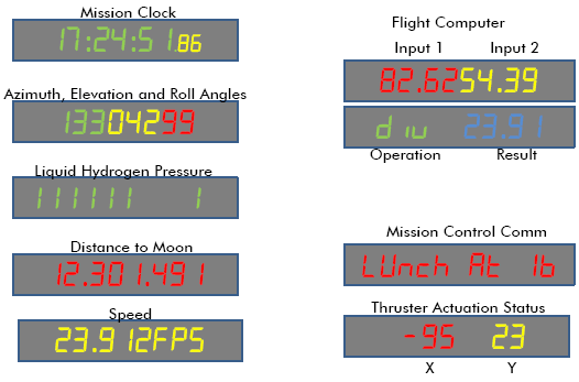
 A few days ago, Jon and I sat down to figure out what the
final rocket control panel should look like. We'd had vague
plans for a while -- a Lunar Distance display here, a
Thruster Actuation Status display there. But last weekend,
Jon, Alex and I actually put the rocket up (see Jon's Oct 18 entry)
so the time finally
came to decide exactly which displays would go where, and in
what colors and sizes.
A few days ago, Jon and I sat down to figure out what the
final rocket control panel should look like. We'd had vague
plans for a while -- a Lunar Distance display here, a
Thruster Actuation Status display there. But last weekend,
Jon, Alex and I actually put the rocket up (see Jon's Oct 18 entry)
so the time finally
came to decide exactly which displays would go where, and in
what colors and sizes.
I used PowerPoint to draw a dozen different proposed panel modules. Then, one evening after work, Jon and I clambered into the newly risen rocket with a dozen correct-scale printouts of a rocket panel. We cut each module out and pasted the ones we liked all around us. I have to say, seeing all those displays up in the rocket, even though they were just paper, was pretty exciting.
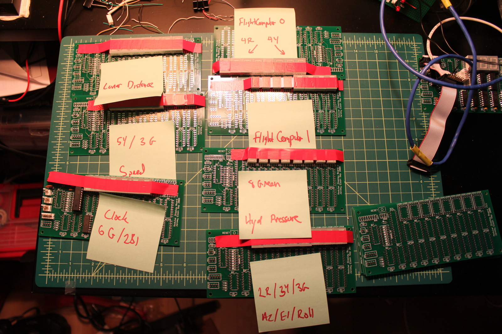
Tonight, I started the process of building all the final boards --
labelling each one with its intended function, and taping all the
right colors and sizes of LEDs into it. It feels like we're almost there!
December 6, 2009 -- The Power Board
 I took a break from rocket work for about a month;
it was taking too much time and
energy
away from "real" work projects.
But, in the past few days, I've been getting back to it.
Oh dear rocket, you lovable little scamp, I could never stay mad at
you!
In the intervening weeks, Jon finalized all the rocket software
and populated 4 of the circuit boards, so things feel like
they're much closer to done now anyway.
I took a break from rocket work for about a month;
it was taking too much time and
energy
away from "real" work projects.
But, in the past few days, I've been getting back to it.
Oh dear rocket, you lovable little scamp, I could never stay mad at
you!
In the intervening weeks, Jon finalized all the rocket software
and populated 4 of the circuit boards, so things feel like
they're much closer to done now anyway.
Yesterday, I went to Jon's house to help him pull wires through the trench he'd built between the rocket and the basement. The trench will carry compressed air and water for the thrusters, power for the boards, and data between the house and the rocket. (The rocket has more utilities coming into it than my apartment!)
We realized that the next step on the critical path was building a board that would distribute power from the house supply out to all the various panels. We'd planned on having such a board from the beginning -- I ordered the necessary components from Digi-Key 3 months ago -- but hadn't needed to put them together until today.
I had a busy weekend, so only had an hour or so for board-building
time. I thought for a while about the best way to construct the
power board, drew a schematic, threw it out, drew a 2nd one,
and then prototyped it on a breadboard. It'll have
a big red power switch, two indicator LEDs,
12 5.5V outputs and 3 12V outputs, with room for
future expansion.
Some evening this week I'll build the real board.
December 9, 2009 -- Final Power Board
 Tonight I soldered together the final power board.
It works!
Tonight I soldered together the final power board.
It works!
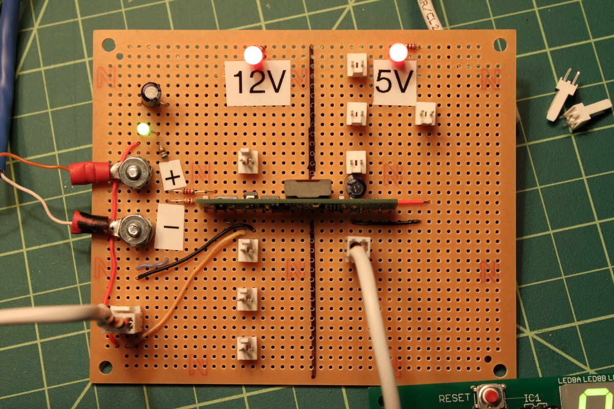
On the far left is the input section. We'll terminate the Romex cable coming through the conduit from Jon's house with a couple of ring terminals that will attach to the board with screws. The input is 12V; a green LED shows that house power is on. Lower left is a 3-pin terminal where we'll attach the master power switch. That will feed power to both of the output sections: 12V and 5V. The 12V output section is just the raw house power, switched but unregulated. It will feed the cockpit lights and the HPAM -- which, in turn, switches power to the thrusters and paint shaker. Power for the 5V output is generated by a switching power regulator and will be used for all the avionics panels. Both output sections have red LEDs showing they're active. Right now the 5V output section only has 5 connectors, but that's just because I ran out of connectors. There's room for 18.
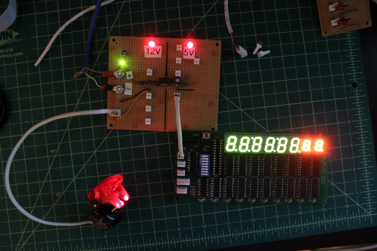
The photos on the right both show the new power board. The second photo shows the new board powering the mission clock panel and was taken with the lights off making the LEDs more clearly visible. Wow, those hundreths-of-a-second LEDs are ridiculously bright! Good thing we moved them from my office wall (where they're distracting) to the rocket (where they're just pure awesome).
December 17, 2009 -- All boards assembled
 Over the past few days I've been soldering together
the rest of the final rocket panel boards.
Jon put together the 4 boards for his awesome
matrix
display;
I've been gradually assembling the other 8.
In reality this was a form of procrastination:
I really need to design the audio board,
but that requires some careful thought.
Late at night just before bed, it's easier to do some
thoughtless assembly rather than circuit layout.
Pictured at right are the final boards:
Over the past few days I've been soldering together
the rest of the final rocket panel boards.
Jon put together the 4 boards for his awesome
matrix
display;
I've been gradually assembling the other 8.
In reality this was a form of procrastination:
I really need to design the audio board,
but that requires some careful thought.
Late at night just before bed, it's easier to do some
thoughtless assembly rather than circuit layout.
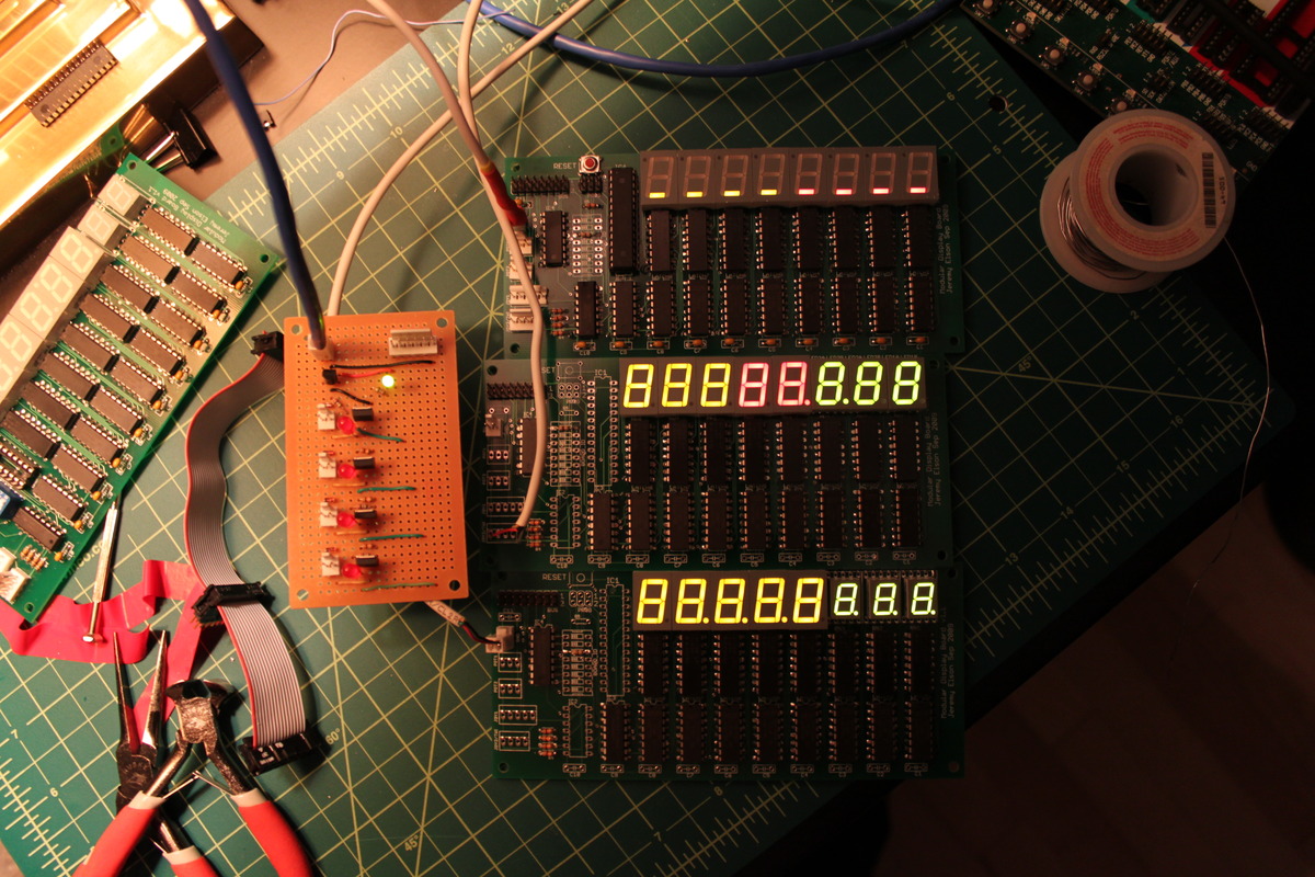
Pictured at right are the final boards:
- (top) One of the two Flight Computer displays;
- (center) Azimuth, Elevation and Roll Angles;
- (bottom) Lunar Speed;
- (left) The second HPAM board for controlling 12V equipment.
Jeremy Elson -- jelson, at the domain: gmail dot com