Building Avionics for a Rocket Ship Treehouse
Page 2
September 10, 2009 -- PCB Layout v1.1
I was so excited about getting the boards sent out that I started revising the design even before the first batch arrived!The biggest difference in v1.1 is that the board now supports two different sizes of 7-segment LED displays. The original board only supported 0.39" high digits, because they're cheapest. But there are a couple of models of cheap 0.56" high digits too, which, being bigger, are naturally cooler. For maximum coolness, we really wanted to be able to mix up the sizes -- have a wall with digits in a variety of colors and sizes. But, for simplicity, we only wanted a single board, so our idea was to have a board that has two sets of mounting holes (and associated traces), fitting both sizes. This version of the board now has this feature. It mainly required learning how to extend the parts library in my PCB design software, since this particular type of 7-segment display wasn't in its pre-defined library.
 And, hats off to Lite-On, the manufacturer of these LEDs. Their pin
layouts really makes board design a lot easier. One, their two anode
pins are 3 and 8, which are the middle pins in both rows. This means
two good things: first, the supply line can run horizontally all the
way across the board, without any turns. Second, you can mount LEDs
upside-down, which is useful to make a clock (mounting every other
digit upside-down gives you a series of colons, rather than decimal
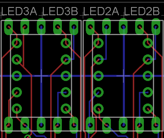
points). Also, even though their 0.56" LEDs have horizontal rows of
pins, rather than vertical as in the 0.39" version, the segments are
controlled by pins in the same quadrant, making the superimposition I
was trying to do quite easy. And the supply lines end up being simple
vertical tendrils off the long horizontal supply line for the smaller
LEDs. The extra traces were all quite short
and didn't intersect with each other. At right is a screenshot of two
adjacent digit positions, each of which is a 0.39" and 0.56" LED
superimposed so that either can be mounted.
And, hats off to Lite-On, the manufacturer of these LEDs. Their pin
layouts really makes board design a lot easier. One, their two anode
pins are 3 and 8, which are the middle pins in both rows. This means
two good things: first, the supply line can run horizontally all the
way across the board, without any turns. Second, you can mount LEDs
upside-down, which is useful to make a clock (mounting every other
digit upside-down gives you a series of colons, rather than decimal
points). Also, even though their 0.56" LEDs have horizontal rows of
pins, rather than vertical as in the 0.39" version, the segments are
controlled by pins in the same quadrant, making the superimposition I
was trying to do quite easy. And the supply lines end up being simple
vertical tendrils off the long horizontal supply line for the smaller
LEDs. The extra traces were all quite short
and didn't intersect with each other. At right is a screenshot of two
adjacent digit positions, each of which is a 0.39" and 0.56" LED
superimposed so that either can be mounted.
I learned lots of other new features of my schematic editor, which let me do other cool things:
- Per-IC capacitors. JD warned me that each IC should really have a cap. However, I couldn't figure out how to do this before, since when I made a row of caps next to each other, the auto-router routed the caps to each other, rather than having each lead of the cap going to the relatively far-away Vcc pin of each IC. Finally, I figured out how to manually route traces, and was able to put the caps in properly. Also, in v1.0 I'd accidentally and incorrectly used the footprint of a capacitor that looks like a miniature oil drum, rather than the M&M-shaped caps I was actually using. This is fixed in v1.1 too.
- Wider power and ground leads. JD warned me I should use wider leads for power and ground, but an online trace-width calculator told me that 6 mil was good enough, and the traces were already 10 mil. Yesterday I realized that the boards I ordered were 1oz copper, but the calculator's default value is 2oz copper and the power leads should have been 12 mil. I widened them, and made all the other leads a narrower 6 mil to save space. (Eagle makes it super easy to say "make the following nets 12 mils wide".)
- Silkscreening. I hadn't bothered to learn how to do a silkscreen layer before sending the first boards out, but once I figured it out, I put nice little labels on all the headers (e.g. PWR, BUS, PROG). I also added credits :-).
- Mounting holes. Oops! I realized after I sent the boards off that I had neglected to add holes that could be used to mount the board to a panel (or standoff). The v1.1 board has mounting holes.
- A square board. Yeah, long story, but, Eagle's snap-to-grid feature acts a little unusually, and the dimensions of my v1 board ended up being something like 6.50032234 inches by 2.30002451 inches, with non-square corners. I figured out how to enter nice round dimensions and fixed it.
I also blew another $75 at DigiKey today, getting enough ICs to build 3 fully-populated 8-LED boards (when the v1.0 PCBs arrive), and some other odds and ends. In particular, 4 electronic potentiometers so that the microcontroller can control the needle on a car gauge, and some manual knob potentiometers so the kids can twirl some knobs. I have a board design in mind to support the gauges, but that'll have to wait for another post.
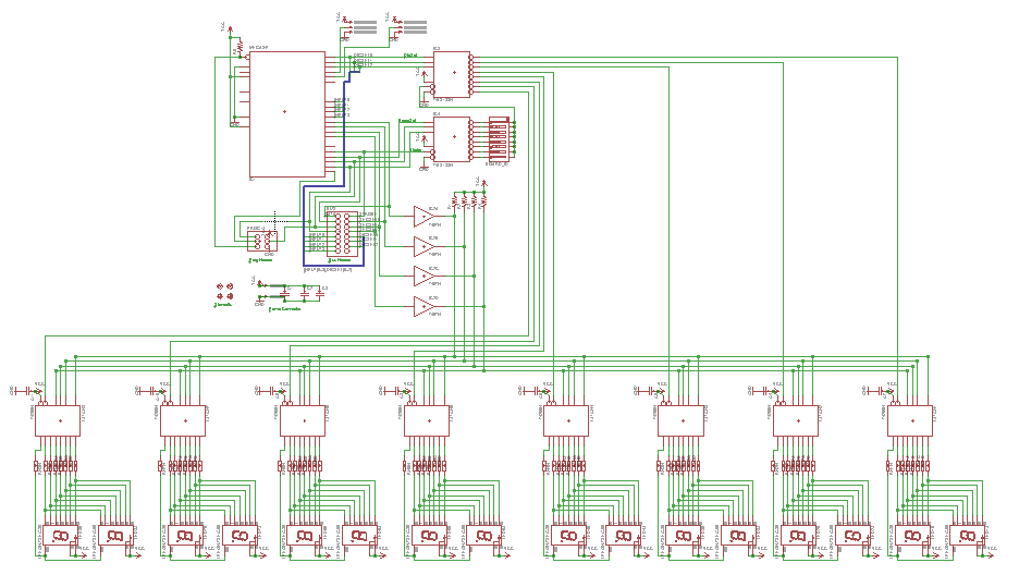
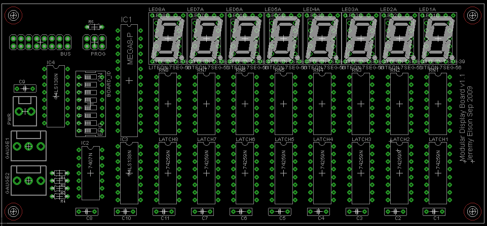
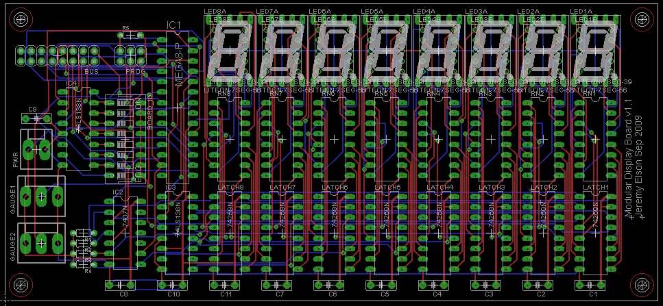
Here's the latest schematic and board layout, both with and without the traces visible.
September 12, 2009 -- A Simulator
 For the past few days I've been thinking more seriously about the
software that will run in the rocket. I wanted to figure out two
things. First, what kind of software will be fun and thematic?
It has to do something interesting that exploits all the interesting
capabilities of the hardware.
Second, what's the right software structure that will let us add
features and models without the code turning into spaghetti?
Luckily, software is my specialty; it's the hardware stuff that's so
alien to me.
For the past few days I've been thinking more seriously about the
software that will run in the rocket. I wanted to figure out two
things. First, what kind of software will be fun and thematic?
It has to do something interesting that exploits all the interesting
capabilities of the hardware.
Second, what's the right software structure that will let us add
features and models without the code turning into spaghetti?
Luckily, software is my specialty; it's the hardware stuff that's so
alien to me.
Sure, the hardware's not here yet. But, since when is a lack of completed hardware an excuse not to work on the software? I spent an hour or two writing a little Rocket Panel Simulator that runs on the console under Linux. It's essentially just a display module that I can link against the same code that goes on the real rocket. When the code is compiled in simulator mode, the functions that assert real I/O pins are replaced with functions that interact with my simulator module.
To the right is a screenshot of the simulator, configured to display 6 8-digit numbers, running the digit-identification program.
I also made some minor updates to the schematic and board layout yesterday. Primarily, I corrected the footprint of the dial connectors. Since the real footprints are smaller, there was also space to add a 3rd one. I also found the connectors at DigiKey that match the templates I used on the v1 boards. If the boards actually work, I may as well just buy the connectors that fit on the boards instead of doing something hacky.
One feature I added to the PCB at the last minute was a couple of
headers for analog inputs. Each header has 3 wires: power, ground,
and a line back to one of the controllers' ADC inputs. I hoped that by
attaching those three leads to a potentiometer, I'd be able to read
the position of a dial.
Unfortunately I didn't actually get a chance to test this before
sending the PCBs out to be produced.
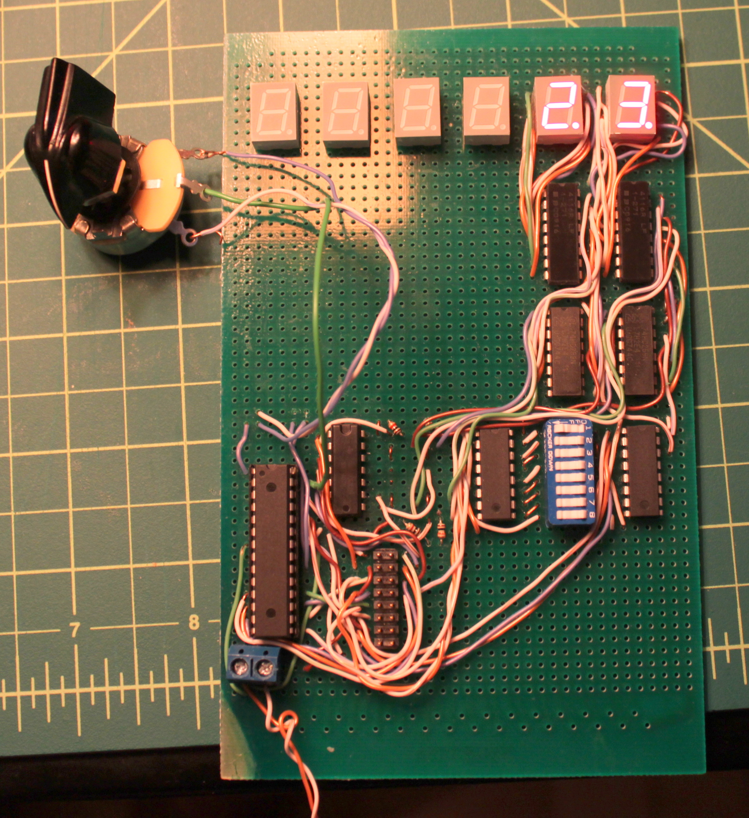
I ordered a bunch of panel-mount 50k
pots that arrived yesterday, and scrounged a rocket-looking knob out
of the hardware lab at work. This evening I tried hooking them up to
my proto-board, and wrote a few lines of code that would read the
analog input once every 50msec, scale it to a value from 0 to 99, and
display that value on the two LEDs on my protoboard. Amazingly, it
worked (almost) without a hitch!
(The only hitch: the ADC input I was using is the same pin as one of
the general purpose input/output pins. I had set all I/O pins as
output pins, so a low value was being asserted on the same pin the ADC
was trying to read, and always returned 0 -- except when the pot was
at such a high value that it overcame the internal resistance of the
output pin. When I reconfigured the GPIO as an input pin, everything
worked.)
One motivation for doing this is that Jon I were scheming
today a way to attach a joystick (which is basically 2 pots attached
to a lever) to the microcontroller. As the pilot moves the joystick,
the microcontroller
outputs will electrically control the solenoid air
valves that actuate the thrusters and paint-shaker. I'll write more on this once
we flesh it out.
I'd hoped that the 2nd batch of PCBs would have only tiny revisions
compared to the first, to minimize the chance of introducing new bugs. But
the changes are pretty substantial at this point. Oh well!
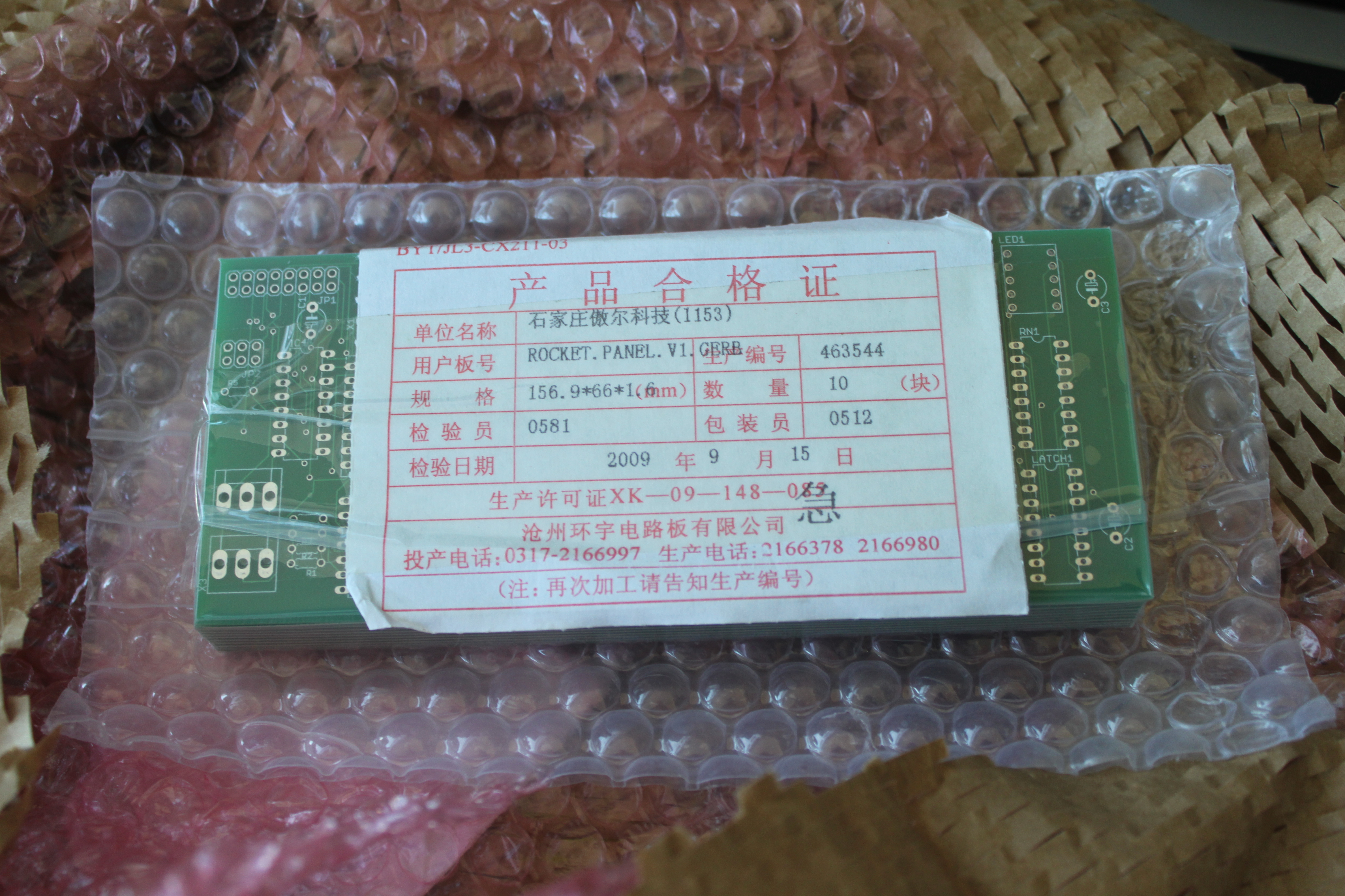
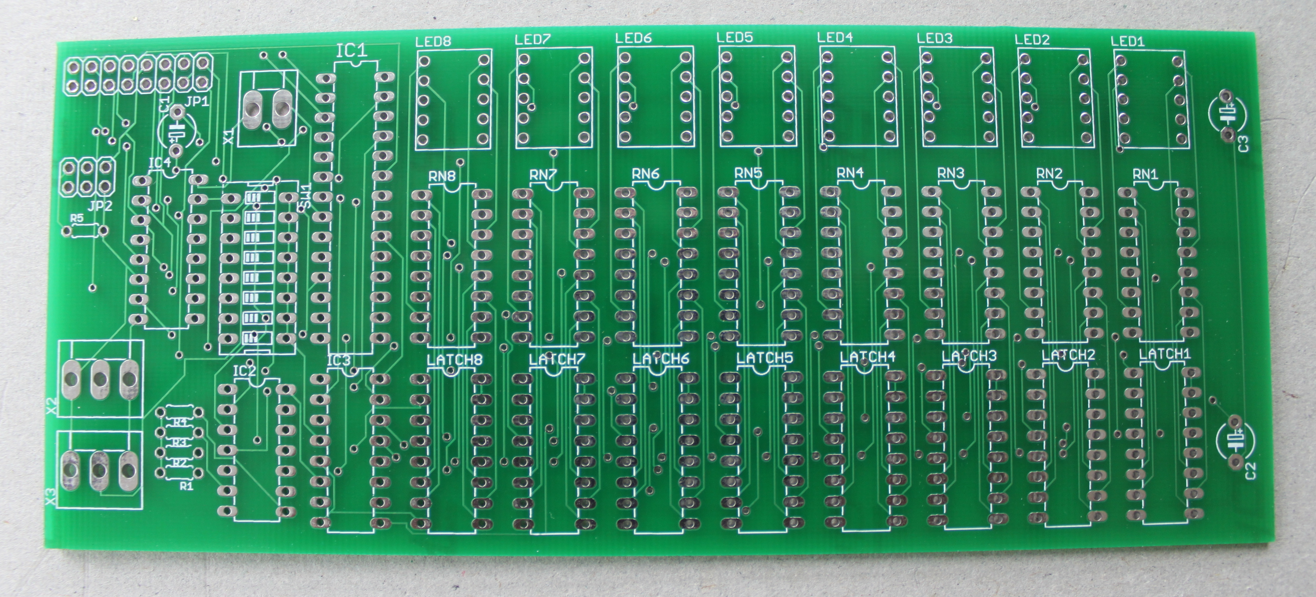
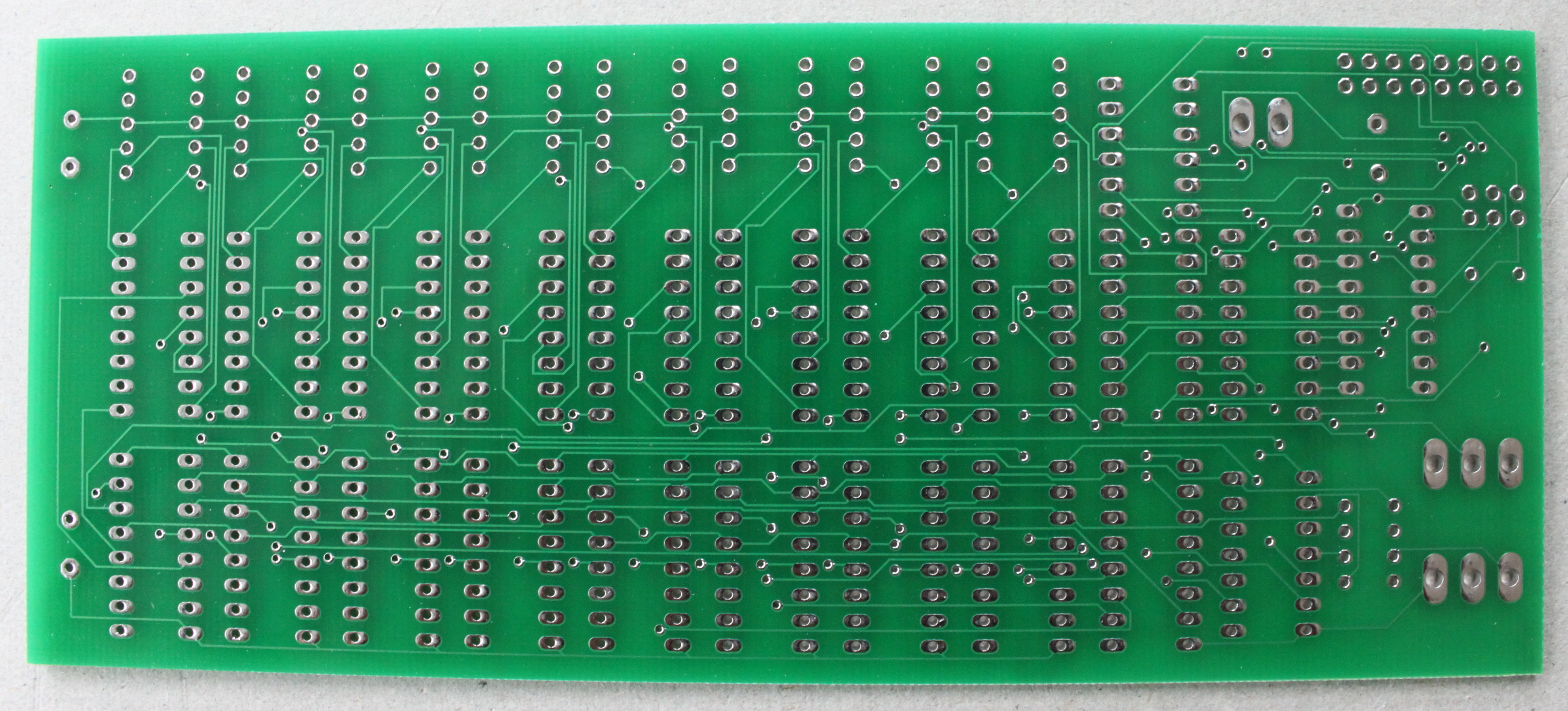
There it is, hot off the Chinese presses -- v1 of the Rocket Panel
Printed Circuit Board!
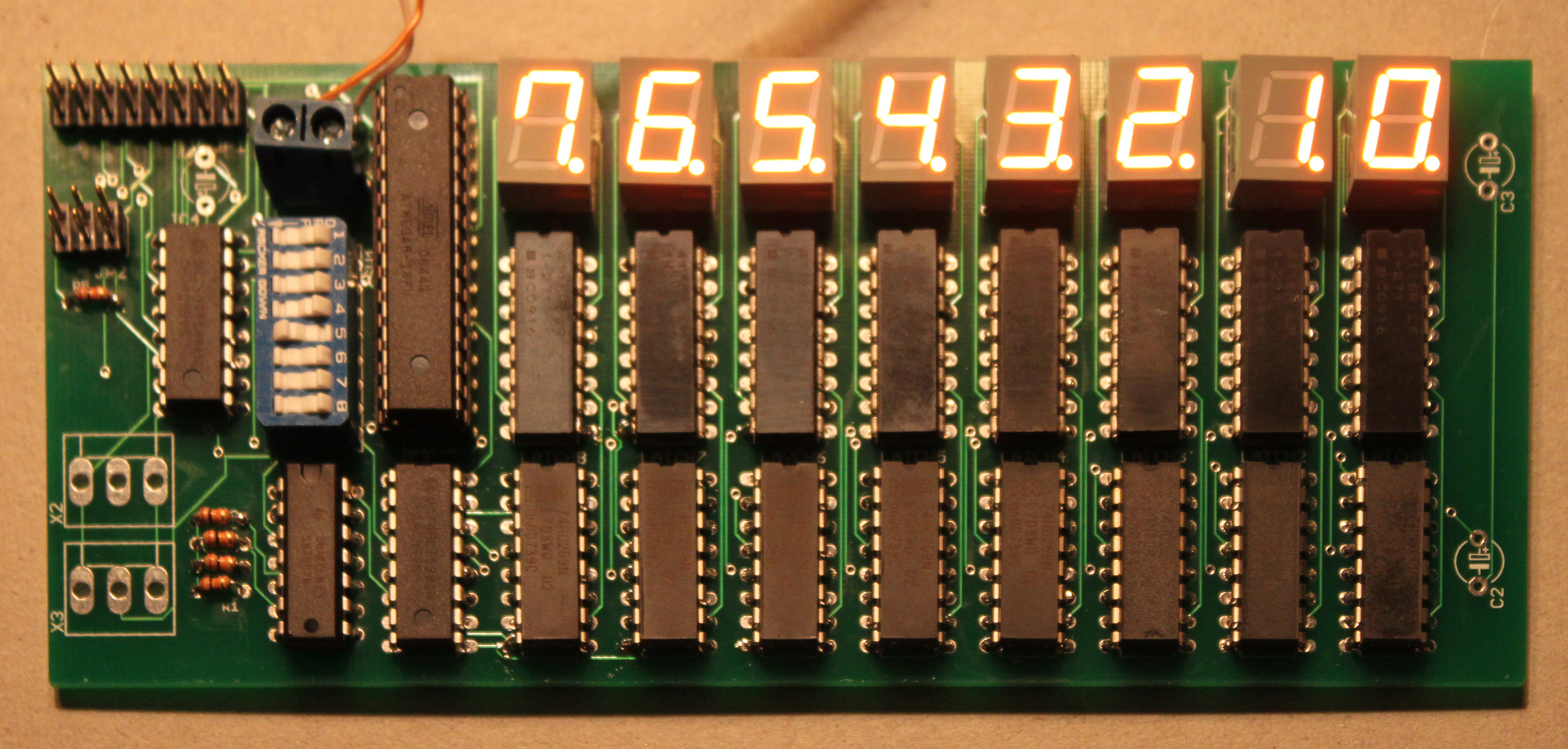
I soldered all the components on,
loaded the digit-identifying program onto a new microcontroller,
popped it in, and turned it on. It worked on the first try!
Isn't it beautiful?
But wait, there's more! I soldered half of a second board together
(alas, I had only 4 LEDs left) and put together a 16-pin ribbon cable
a few inches long. I connected the two bus connectors and -- voila!
Both boards are being controlled by a single processor!
As if that wasn't all cool enough, the programming header works, too!
I was able to put new code on the microcontroller in place by just running
a cable from the programming kit board to the programming header on my PCB.
Total success!
There was one minor board bug I discovered even before receiving the
boards: a wire I was supposed to connect, but didn't, that's needed to
read from analog dials. But that's easy to manually fix.
Despite the fact that (amazingly) these boards work, I think I'm still
going to order the v1.1 boards. They have lots of nice features, such
as mounting holes, support for larger LEDs,
support for 6 dials rather than just 2 (important
because of our joystick, as I described on Sep 16th), and
some other odds and ends.
Still on the To-Do list:
Can you believe I'm running out of solder? That's like running out of
baking soda. I think I've had my current spool of solder since I was
in college.
Bang!
It's not too hard to find cheap used car gauges on Ebay. A couple
of months ago, I paid all of $0.99 (shipping included!) for
really
cool-looking electroluminescent
oil temperature and RPM gauges.
We thought they'd be perfect for the rocket's control panel.
Unfortunately, we couldn't figure out how to get them to do
anything. They'd power up when attached to a 12V supply, but we
couldn't figure out what kind of signal to put on the sense line to
get the needle to move.
I learned that car part manufacturers don't document their interfaces
as meticulously as most other electronics components. If you go onto
Digi-Key and buy so much as a 7 cent LED, it'll come with 8 pages of
documentation, exhaustively describing its electrical and mechanical
properties. Car gauges seem to come with nothing more than a flyer
that says "Put 'er in your car! Then go get a cigarette! Yee haw!"
After hours of web research I found a catalog page for a 3rd party
fuel-tank sensor that said "Attaches to standard gauge (60 ohm full -
600 ohm empty)." At last, some data! Apparently you vary the
resistance on that signal wire. I tried attaching our fancy gauges
to a pot with the proper range but the needle still didn't budge.
Finally, I speculated that perhaps the gauges were broken and that's
why they cost $0.99. Jon took me on my first trip to a junkyard,
charmingly named Pull-a-Part, and I
paintakingly extricated a couple of gauges out of the dash of an
Oldsmobile (I think). Hooked that up to a mechanical pot,
and when I adjusted it with a screwdriver,
the needle moved. Hooray!
It's too bad those gauges are so ugly. The broken
EL gauges looked rocket-y; the ones that work just scream "80s sedan".
That brings us to today. How do you get a microcontroller to provide
variable resistance? I discovered a clever device called a digital
pot that does exactly that: every time you strobe one of its pins,
it increases (or decreases, your choice) its resistance among 100
pre-set values. Easy, right? I ordered a few of them last week,
and today tried to get one working.
Fourth try: the microcontroller and pot were powered off different
halves of my power supply; maybe their grounds are floating relative
to each other? I tied the two grounds together,
and, success! I can now get the pot to increase its
resistance by 10 ohms at a time.
Fifth try: I hooked the pot up to the actual gauge rather than an
ohmmeter. Everything broke; when I put the ohmmeter back, the
resistance was 10 kohm (even though the pot is only rated to go up to a
max of 1 kohm!). Tried with a 2nd digital pot; worked with the
ohmmeter,
then broke when attached to a gauge. I took another look at the
datasheet, and realized that the pot was only rated for 5v across its
terminals at a max of 1 milliamp. What the hell use
is that to anyone? The gauge has 12v from its its sense line
to ground and when I hooked it up to an ammeter, it was pushing 250ma
through it. Obviously I was just destroying the digital pots.
So ends the saga for now. I need to order some beefier digital pots
and try again.
September 15, 2009 -- Analog Dials
A rocketship just wouldn't be a rocketship without some dials to
turn. I mean, how else are you going to adjust your fuel flow and
tune your navigational radio? With a keyboard? Puh-leeze.
September 16, 2009
I did a major revision of the schematic this evening, primarily because of
yesterday's fantastic success with the analog dials. I wanted
all the analog-to-digital converter inputs to be
available to attach to pots. I completely changed the assignment of
logical output pins (e.g. segment select 0-2) to physical pins on the
microcontroller so that none of the ADC pins are used for generic
digital I/O any more. Then I brought all the ADC pins out to
their own headers.
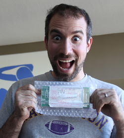
September 19, 2009 -- v1 PCBs Arrived!!
Guess what was waiting for me when I got home from work yesterday?
September 20, 2009
It's 1am Sunday. I've hacked on the boards all day (Saturday) and
it's really incredible: they work. I tested
This evening, Jon was so excited that he used the simulator to write a
ton of code that would make modules easy to write, and finally wrote a
module that would scroll a message across the LEDs. After a little
tweaking I got it to run on the real hardware:
September 21, 2009 -- The gauge fiasco
Today I worked on the one part of this project that has
been consistently dogged by failure: getting analog gauges attached to
the rocket.
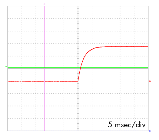
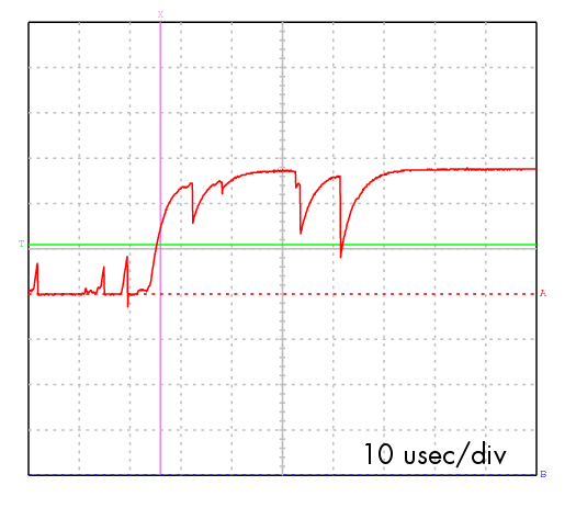 First try: breadboarded a prototype, using buttons to strobe the
inputs, and measuring the outputs with an ohmmeter. Seemed to work,
but jumped forward a lot every time I pushed the button. My little
oscilloscope confirmed that button bounce was my problem (right).
First try: breadboarded a prototype, using buttons to strobe the
inputs, and measuring the outputs with an ohmmeter. Seemed to work,
but jumped forward a lot every time I pushed the button. My little
oscilloscope confirmed that button bounce was my problem (right).
 Second try:
I attached a capactior and a couple of series resistors such that
the cap would slowly charge and discharge, smoothing the signal.
It was sure nice and smooth, and was asserted far more slowly
(milliseconds rather than microseconds), but the pot still jumped
forward by several steps with each button press. Perhaps
I need a smaller cap so the voltage doesn't camp out near the
threshold for as long?
Second try:
I attached a capactior and a couple of series resistors such that
the cap would slowly charge and discharge, smoothing the signal.
It was sure nice and smooth, and was asserted far more slowly
(milliseconds rather than microseconds), but the pot still jumped
forward by several steps with each button press. Perhaps
I need a smaller cap so the voltage doesn't camp out near the
threshold for as long?
Third try: hooked the thing up to a microcontroller that did nothing
but strobe pins. I hoped the controller would give cleaner
transitions than my mechanical button. Much to my amazement,
the pot seemed to just slide between its two extremes. What is going
on?
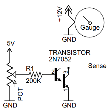 Now, on to gradually reducing this current all the way to zero,
so the gauge goes through its range of deflections.
The easiest way to do this (rather than hugely increasing the base
resistance)
is to reduce the base voltage, using a pot configured
as a voltage divider. That is, 5v and gnd on the top and bottom,
of the pot
and the base
resistor attached to the wiper, as shown in the diagram to the right.
I hooked up one of my mechanical pots and, sure enough, turning the
pot got the gauge to gradually move between its two extremes!!
Now, on to gradually reducing this current all the way to zero,
so the gauge goes through its range of deflections.
The easiest way to do this (rather than hugely increasing the base
resistance)
is to reduce the base voltage, using a pot configured
as a voltage divider. That is, 5v and gnd on the top and bottom,
of the pot
and the base
resistor attached to the wiper, as shown in the diagram to the right.
I hooked up one of my mechanical pots and, sure enough, turning the
pot got the gauge to gradually move between its two extremes!!
|
|
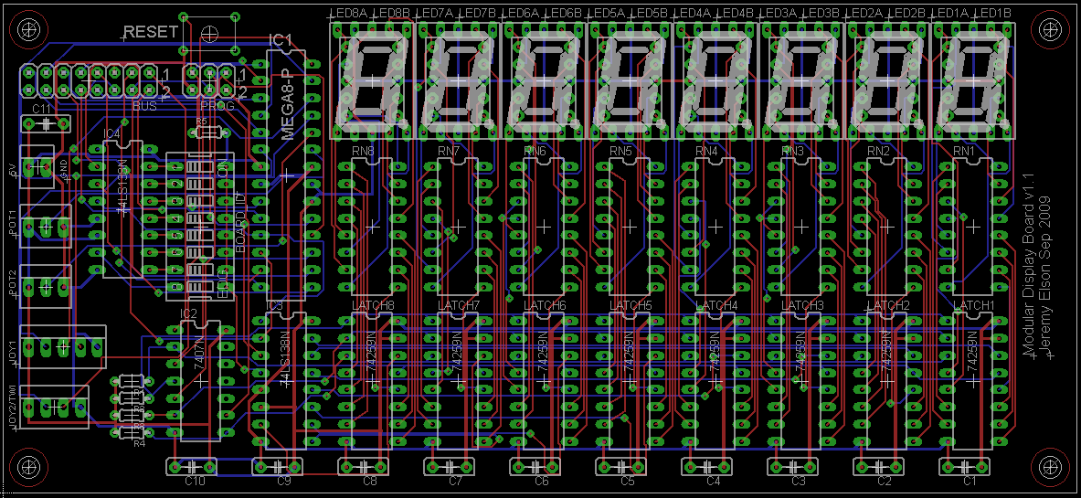
| v1.1 of the PCB -- schematic and board layout |
I also added a reset button, some nice silkscreened labels on everything, and more generous clearance between pads and vias to make the boards easier to solder without accidentally shorting two nets.
Ever the eternal optimist, I ordered 20 of these boards -- enough for two full stacks, plus a couple of extra for development, or just hanging on my office wall. Why not, they're less than $3 each (plus $90 setup fee and shipping). They should be here October 5 -- something to look forward to after the NSDI deadline has passed!
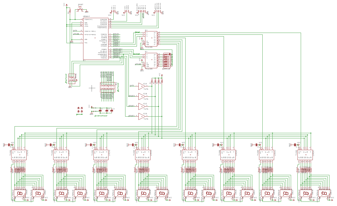
Here's the final schematic and board layout. Note the schematic
is much cleaner once I learned how to attach remote nets just by
giving them the same name; the ugly and not-very-informative
blue bus no longer snakes its way through the center. Plus,
the bus connector's pins are all assigned to a logical name,
rather than a microcontroller pin: exactly how it should be,
since from revision to revision, we want the mapping of the
logical function (e.g., segment select) to position on the bus header
to
remain consistent, but we don't really care which microcontroller pin
is being used to drive the bus.
Today's main project was building a small board that would let the
main rocket panel actuate the rocket's "engine" and "thrusters".
As Jon briefly describes in
his todo
list,
he's going to run compressed air to the rocket from his
garage air compressor. This will power both the rocket's "engines"
(actually a paint shaker that will vibrate the rocket for "takeoff"!)
and its "maneuvering thrusters"
(actually pneumatic engine cleaning guns).
Jon's original plan was to rig up some kind of mechanical valve to let
the pilot turn these systems on and off from the cockpit, but I
convinced him to buy some $18 solenoid air valves I found on EBay.
That gives us the flexibility to have the thrusters controlled both
from software and manually by the pilot We're going to write
some sort of "launch sequence" program that will fire up the engines
and thrusters; once in orbit, the pilot will be able actuate the
thrusters using a joystick.
Jon was resistant to the idea at
first, but as soon as the valves arrived and he saw one
turn on his paint shaker, he
was glad the rocket's electrical and pneumatic systems would be
working as a team!
Since we only needed one or two of these boards, I just made them by
hand rather than getting PCBs professionally manufactured. And,
to really give the thing that 50's Fictional Space Program feel,
we gave the board a ridiculous name: the High Power Auxiliary
Module.
The end result, I must say, is super cool. Here's a video clip of
Liesl playing with the button box. Each button press lights up an
LED. I also attached a test solenoid to Channel 3; if you turn up the
sound you can hear it clicking when she pushes Button 3.
I'm heading to Jon's place tomorrow to try it with a solenoid that has
real air running through it .... how exciting!
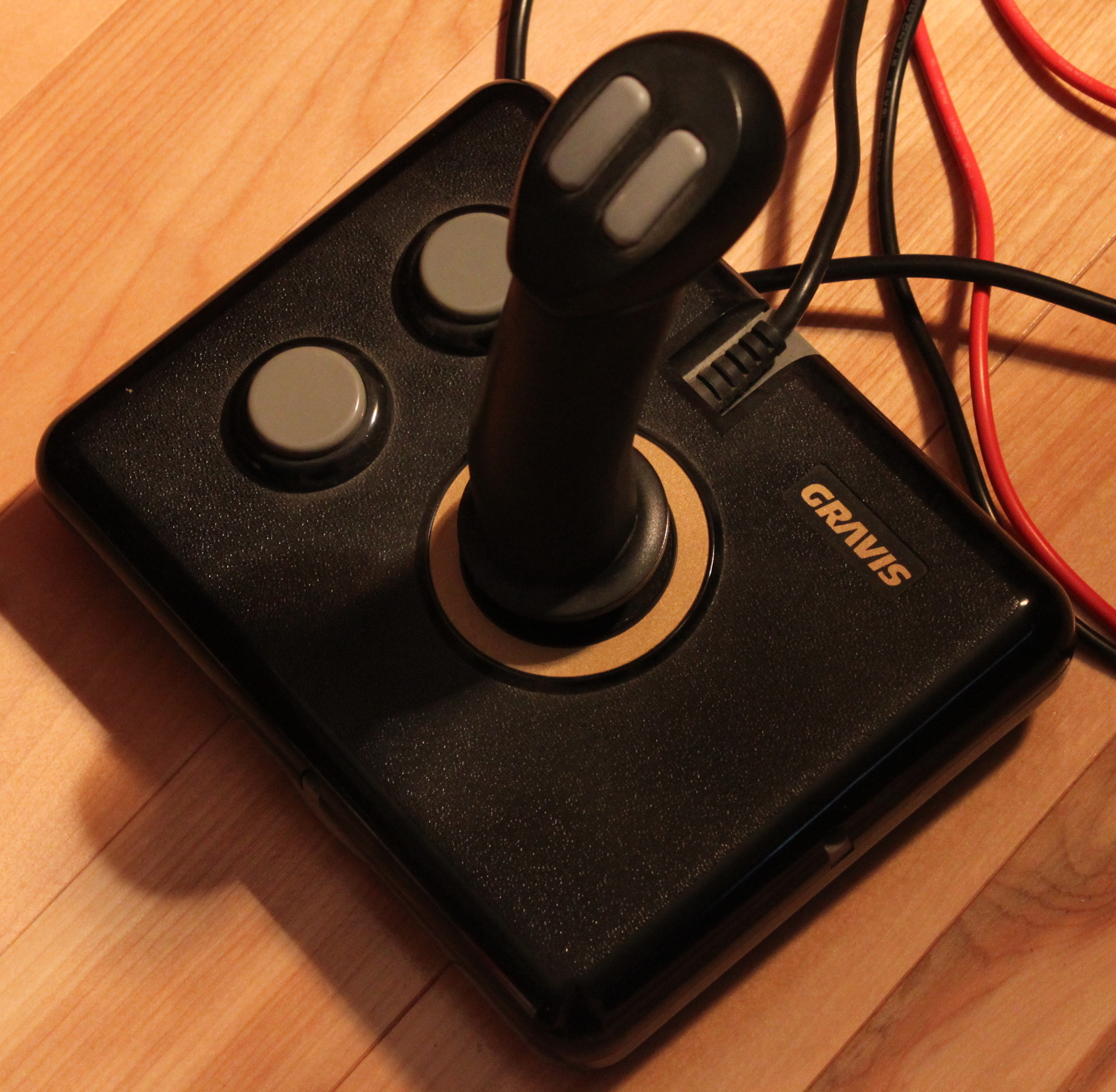
After some research, we discovered that old-style PC joysticks are
actually just two potentiometers, one for the vertical and horizontal
directions. Joystick buttons are just plain old pushbuttons that
ground their inputs. This should make it easy to attach a joystick
to a microcontroller. In theory.
Step one was finding a joystick. Modern joysticks are
digital monstrosities with USB interfaces. We needed a 1990's
era joystick, and they were surprisingly hard to find. No one
uses them any more. Finally, one popped up on Craigslist for $1
nearby in Redmond, so I biked over there after work one afternoon
a couple of weeks ago and picked it up. The 5-year-old previous
owner was excited to hear his old toy was going into a rocket ship.
I promised him a ride once it was finished!
Wait, what am I talking about? Random stray circuit boards
scattered around the rocket will just make it better!
October 4, 2009 -- The High Power Auxiliary Module
My beloved rocket panel got no attention for about 2 weeks
because of an important October 2 work deadline.
But as soon as that passed, back to work!
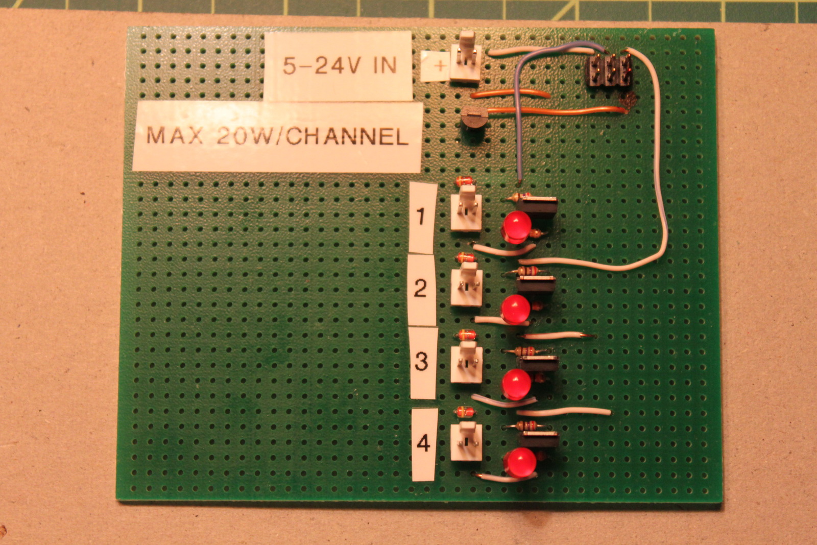 From my point of view, the plan was to choose one of the eight
identical display boards as the controller, leave off one of its LEDs,
and use the 8 unused latch outputs as control signals for 8 valves.
Unfortunately, the latches can only source 25 milliamps at 5 volts,
but the valves need 500 milliamps at 12 volts. The solution: a small
board with
power
MOSFETs,
using 5v control signals to switch the larger 12v valve power. More
for fun than anything else, I also put LEDs on the board that light up
every time one of the channels is active.
From my point of view, the plan was to choose one of the eight
identical display boards as the controller, leave off one of its LEDs,
and use the 8 unused latch outputs as control signals for 8 valves.
Unfortunately, the latches can only source 25 milliamps at 5 volts,
but the valves need 500 milliamps at 12 volts. The solution: a small
board with
power
MOSFETs,
using 5v control signals to switch the larger 12v valve power. More
for fun than anything else, I also put LEDs on the board that light up
every time one of the channels is active.
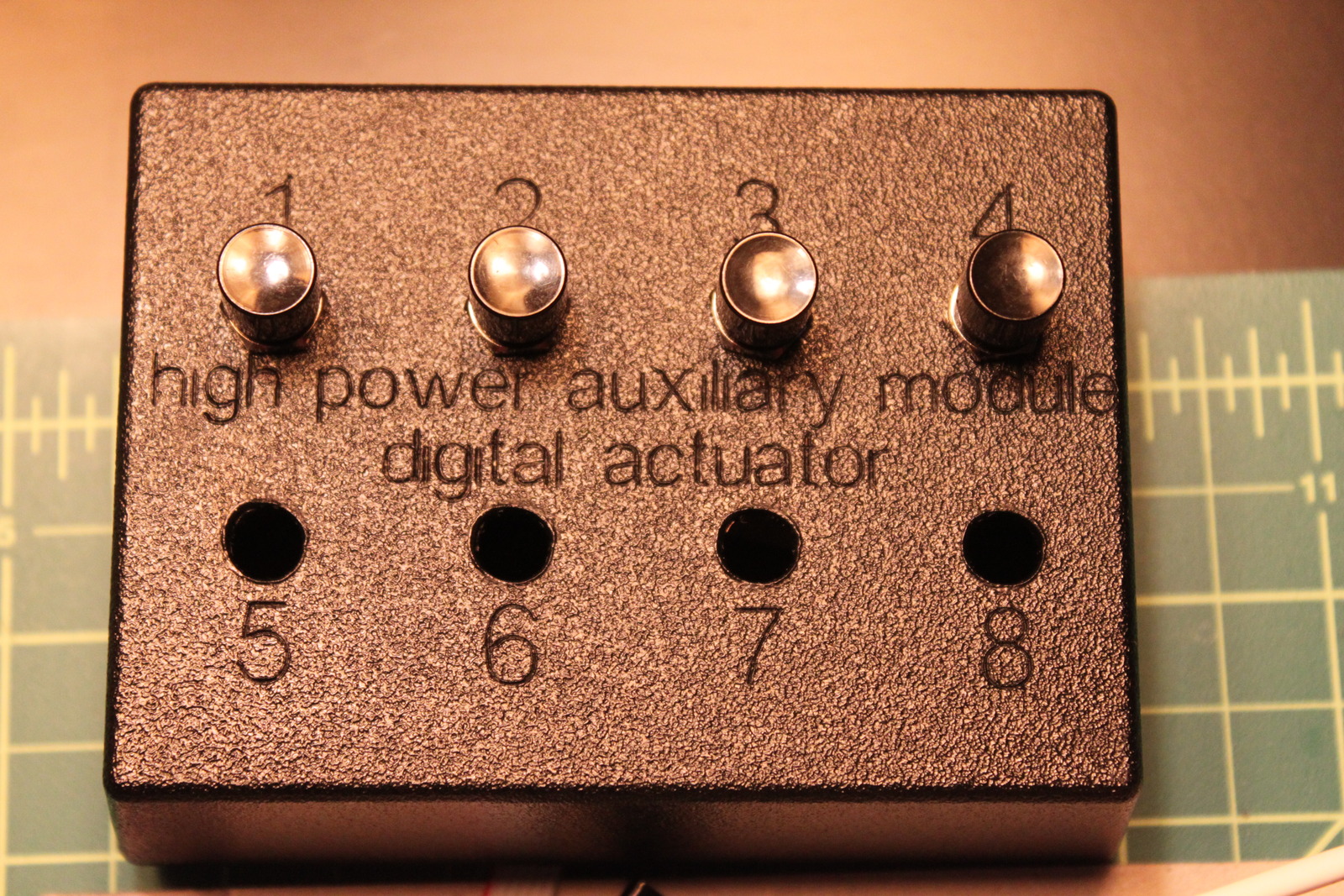 The ultimate plan is to attach them to one of the rocket panel boards.
But, I decided (half for fun, and half because it made good
engineering sense) to build a small box with manual pushbuttons,
and design the HPAM so it could be plugged into either a rocket panel board
or the manual button box. For maximum ridiculousness, I used the
laser cutter at work to cut the 8 button holes and put a Fake Space
Program label on the box. It's the HPAM "Digital Actuator". See,
because you press it with your digits. Your fingers. Get it?
Yeah, not that funny.
The ultimate plan is to attach them to one of the rocket panel boards.
But, I decided (half for fun, and half because it made good
engineering sense) to build a small box with manual pushbuttons,
and design the HPAM so it could be plugged into either a rocket panel board
or the manual button box. For maximum ridiculousness, I used the
laser cutter at work to cut the 8 button holes and put a Fake Space
Program label on the box. It's the HPAM "Digital Actuator". See,
because you press it with your digits. Your fingers. Get it?
Yeah, not that funny.
October 8, 2009 -- Reading a joystick
 Oct 4's entry described how the microcontroller will be able to
actuate the thrusters. But how does the microcontroller
know when?
For it to be fun, the pilot (i.e., kid) needs to be able to actually
"steer". The obvious choice: a joystick!
Oct 4's entry described how the microcontroller will be able to
actuate the thrusters. But how does the microcontroller
know when?
For it to be fun, the pilot (i.e., kid) needs to be able to actually
"steer". The obvious choice: a joystick!
 Tonight I sat down to see if I could get the microcontroller to read
the joystick's position. I thought it would be easy; I assumed that
the top and bottom of the joystick's pot would be attached to +5V and
GND, meaning the output would be some voltage in between, linearly
mapped to the joystick's position, that could be easily read by the
ADC. But... surprise! It turns out that for some reason, joysticks
don't attach the bottom of the pot to GND, they just let it float.
They just vary their resistance, as shown in the diagram to the right.
The resistance varies between 0 and 100k ohms; 50k is center.
Tonight I sat down to see if I could get the microcontroller to read
the joystick's position. I thought it would be easy; I assumed that
the top and bottom of the joystick's pot would be attached to +5V and
GND, meaning the output would be some voltage in between, linearly
mapped to the joystick's position, that could be easily read by the
ADC. But... surprise! It turns out that for some reason, joysticks
don't attach the bottom of the pot to GND, they just let it float.
They just vary their resistance, as shown in the diagram to the right.
The resistance varies between 0 and 100k ohms; 50k is center.
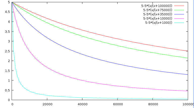 I think the easiest way to sense an unknown resistance when you have
an ADC is to attach a series resistor between the joystick's output
and ground, then read the voltage on the joystick side of that
resistor. The problem is, no resistor value is ideal. This is
illustrated in the plot on the right, which shows joystick position
vs. voltage for 5 different series resistors: 1k, 10k, 35k, 75k, and
100k. The small resistors let you use the entire range of the ADC,
but concentrate most of the precision on a small part of the
joystick's range of motion. Higher values are closer to linear, but
throw away 3/5ths of the ADC's precision across the board since they
only vary by 2 volts. How annoying. I think I'll use the 35k
resistor; that seems like a good balance. Unfortunately, this also
means needing a small interface board between the joystick and rocket
panel with nothing on it but 2 resistors. Again, annoying.
I think the easiest way to sense an unknown resistance when you have
an ADC is to attach a series resistor between the joystick's output
and ground, then read the voltage on the joystick side of that
resistor. The problem is, no resistor value is ideal. This is
illustrated in the plot on the right, which shows joystick position
vs. voltage for 5 different series resistors: 1k, 10k, 35k, 75k, and
100k. The small resistors let you use the entire range of the ADC,
but concentrate most of the precision on a small part of the
joystick's range of motion. Higher values are closer to linear, but
throw away 3/5ths of the ADC's precision across the board since they
only vary by 2 volts. How annoying. I think I'll use the 35k
resistor; that seems like a good balance. Unfortunately, this also
means needing a small interface board between the joystick and rocket
panel with nothing on it but 2 resistors. Again, annoying.